详解交换路由VRRP+MSTP+路由策略综合配置
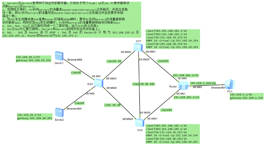
组网要求:
1. Server1及Server2是两种不同业务的服务器,分别处于两个VLAN:10及20。PC1要求能够访问到Server1及Server2;
2.当网络正常时,PC1访问Server1的流量走Router>SW1>SW3>Server1这条路径,并且往返路径一致,而PC1访问Server2的流量则走Router>SW2>SW3>Server2这条路径并且也要求来回路径一致;
3. 当SW1发生故障或者SW1连接Router的链路DOWN掉时,要求PC访问Server1的流量能够自动切换到SW2;同样的当SW2发生故障时,PC访问Server2的流量要能够自动切换到SW1;
4. SW1、SW2、SW3三台交换机构成一个二层环路,运行MSTP防止环路;
5. SW1及SW2为汇聚交换机,Server1和Server2的网关在这两台设备上;
6. SW1 、 SW2 及 Router 运 行 OSPF ; SW1 及 SW2 的 RouterID 分 别 为 192.168.255.11 及192.168.255.12,Router的RouterID为192.168.255.1。
IP设置:
PC1:192.168.1.1/24,网关:192.168.1.254
Server1:vlan10,192.168.10.1/24,网关:192.168.10.254
Server2:vlan20,192.168.20.1/24,网关:192.168.20.254
SW1:vlanif201:192.168.201.1/24vlanif203:192.168.203.1/24vlanif10:192.168.10.253/24VRRP 10 virtual-ip:192.168.10.254vlanif20:192.168.20.253/24VRRP 20 virtual-ip:192.168.20.254SW2:vlanif202:192.168.202.1/24vlanif203:192.168.203.2/24vlanif10:192.168.10.252/24VRRP 10 virtual-ip:192.168.10.254vlanif20:192.168.20.252/24VRRP 20 virtual-ip:192.168.20.254Router:GE0/0/0:192.168.201.2/24,GE0/0/1:192.168.202.2/24,GE0/0/2:192.168.1.254/24
三、配置步骤:
1.所有设备完成基础配置
SW3的配置如下:
[SW3] vlan batch 10 20[SW3] interface GigabitEthernet0/0/1[SW3-GigabitEthernet0/0/1] port link-type access[SW3-GigabitEthernet0/0/1] port default vlan 10[SW3] interface GigabitEthernet0/0/2[SW3-GigabitEthernet0/0/2] port link-type access[SW3-GigabitEthernet0/0/2] port default vlan 20[SW3] interface GigabitEthernet0/0/23[SW3-GigabitEthernet0/0/23] port link-type trunk[SW3-GigabitEthernet0/0/23] port trunk allow-pass vlan 10 20[SW3] interface GigabitEthernet0/0/24[SW3-GigabitEthernet0/0/24] port link-type trunk[SW3-GigabitEthernet0/0/24] port trunk allow-pass vlan 10 20
SW1的配置如下:
[SW1] vlan batch 10 20 201 203[SW1] interface GigabitEthernet0/0/23[SW1-GigabitEthernet0/0/23] port link-type trunk[SW1-GigabitEthernet0/0/23] port trunk allow-pass vlan 10 20[SW1] interface GigabitEthernet0/0/20[SW1-GigabitEthernet0/0/20] port link-type trunk[SW1-GigabitEthernet0/0/20] port trunk allow-pass vlan 10 20 203[SW1] interface GigabitEthernet0/0/21[SW1-GigabitEthernet0/0/21] port link-type access[SW1-GigabitEthernet0/0/21] port default vlan 201[SW1] interface vlanif 10[SW1-vlanif10] ip adderss 192.168.10.253 24[SW1] interface vlanif 20[SW1-vlanif20] ip adderss 192.168.10.252 24[SW1] interface vlanif 201[SW1-vlanif201] ip adderss 192.168.201.1 24[SW1] interface vlanif 203[SW1-vlanif203] ip adderss 192.168.203.1 24
SW2的配置如下:
[SW2] vlan batch 10 20 202 203[SW2] interface GigabitEthernet0/0/24[SW2-GigabitEthernet0/0/24] port link-type trunk[SW2-GigabitEthernet0/0/24] port trunk allow-pass vlan 10 20[SW2] interface GigabitEthernet0/0/20[SW2-GigabitEthernet0/0/20] port link-type trunk[SW2-GigabitEthernet0/0/20] port trunk allow-pass vlan 10 20 203[SW2] interface GigabitEthernet0/0/21[SW2-GigabitEthernet0/0/21] port link-type access[SW2-GigabitEthernet0/0/21] port default vlan 202[SW2] interface vlanif 10[SW2-vlanif10] ip adderss 192.168.10.252 24[SW2] interface vlanif 20[SW2-vlanif20] ip adderss 192.168.10.253 24[SW2] interface vlanif 202[SW2-vlanif202] ip adderss 192.168.202.1 24[SW2] interface vlanif 203[SW2-vlanif203] ip adderss 192.168.203.2 24
Router的配置如下:
[Router] interface GigabitEthernet 0/0/0[Router-GigabitEthernet0/0/0] ip address 192.168.201.2 24[Router] interface GigabitEthernet 0/0/1[Router-GigabitEthernet0/0/1] ip address 192.168.202.2 24[Router] interface GigabitEthernet 0/0/2[Router-GigabitEthernet0/0/2] ip address 192.168.1.254 24
PC、Server1及Server2的配置这里不再赘述。
2.完成SW1、SW2及SW3的MSTP+VRRP配置
为了满足题目的需求,我们将VLAN10及VLAN20分别映射到MSTP实例1和实例2,然后将SW1设置为实例1的主根、实例2的次根,而SW2设置为实例2的主根、实例1的次根。同时在SW1及SW2上均部署两组VRRP,在VLAN10上部署的这组VRRP中SW1为Master,而在VLAN20上部署的这组VRRP中SW2为Master。这是典型的MSTP+VRRP解决方案。
SW3的配置如下:
#配置MSTP,将vlan10映射到实例1,将vlan20映射到实例2:
[SW3] stp mode mstp[SW3] stp region-configuration[SW3-mst-region] region-name huawei[SW3-mst-region] instance 1 vlan 10[SW3-mst-region] instance 2 vlan 20[SW3-mst-region] active region-configuration[SW3-mst-region] quit[SW3] stp enable
SW1的配置如下:
[SW1] stp mode mstp[SW1] stp region-configuration[SW1-mst-region] region-name huawei[SW1-mst-region] instance 1 vlan 10[SW1-mst-region] instance 2 vlan 20[SW1-mst-region] active region-configuration[SW1-mst-region] quit[SW1] stp instance 1 root primary[SW1] stp instance 2 root secondary[SW1] stp enable[SW1] interface Vlanif 10[SW1-vlanif10] vrrp vrid 10 virtual-ip 192.168.10.254[SW1-vlanif10] vrrp vrid 10 priority 120[SW1-vlanif10] vrrp vrid 10 track interface GigabitEthernet 0/0/21 reduced 30[SW1] interface Vlanif 20[SW1-vlanif20] vrrp vrid 20 virtual-ip 192.168.20.254
SW2的配置如下:
[SW2] stp mode mstp[SW2] stp region-configuration[SW2-mst-region] region-name huawei[SW2-mst-region] instance 1 vlan 10[SW2-mst-region] instance 2 vlan 20[SW2-mst-region] active region-configuration[SW2-mst-region] quit[SW2] stp instance 1 root secondary[SW2] stp instance 2 root primary[SW2] stp enable[SW2] interface Vlanif 10[SW2-vlanif10] vrrp vrid 10 virtual-ip 192.168.10.254[SW2] interface Vlanif 20[SW2-vlanif20] vrrp vrid 20 virtual-ip 192.168.20.254[SW2-vlanif20] vrrp vrid 20 priority 120[SW2-vlanif20] vrrp vrid 20 track interface GigabitEthernet 0/0/21 reduced 30
完成上述配置后,先做一下基本的验证:
[SW3] display stp briefMSTID Port RoleSTP StateProtection0 GigabitEthernet0/0/1 DESIFORWARDING NONE0 GigabitEthernet0/0/2 DESIFORWARDING NONE0 GigabitEthernet0/0/23 ROOT FORWARDING NONE0 GigabitEthernet0/0/24 DESI FORWARDING NONE1 GigabitEthernet0/0/23 ROOT FORWARDING NONE1 GigabitEthernet0/0/24 ALTE DISCARDING NONE2 GigabitEthernet0/0/23 ALTE DISCARDING NONE2 GigabitEthernet0/0/24 ROOT FORWARDING NONE
从SW3的生成树接口状态输出可以看到,对于MSTP实例1,SW3的GE0/0/24接口处于丢弃状态,而对于MSTP实例2,SW3的GE0/0/23接口处于丢弃状态。因此VLAN10的流量从SW3的GE0/0/23接口进出,而VLAN20的流量从GE0/0/24接口进出。
[SW1]display vrrp brief
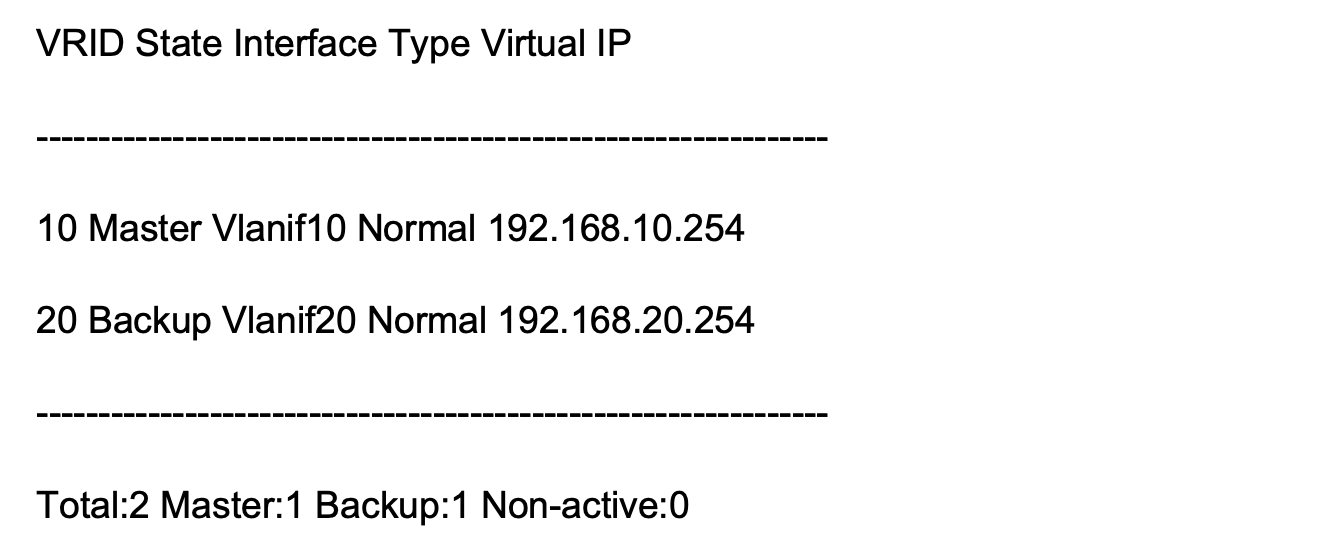
SW1的VRRP状态也是正确的,它是VRRP组10的Master,同时也是VRRP组20的Backup。
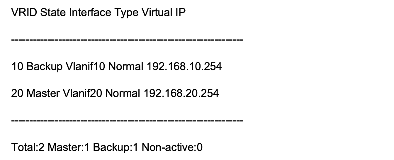
[SW2]display vrrp brief
完成SW1、SW2、SW3及Router的OSPF基础配置
SW1的配置如下:
[SW1] ospf 1 router-id 192.168.255.11[SW1-ospf-1] area 0[SW1-ospf-1-area-0.0.0.0] network 192.168.201.0 0.0.0.255[SW1-ospf-1-area-0.0.0.0] network 192.168.203.0 0.0.0.255
SW2的配置如下:
[SW2] ospf 1 router-id 192.168.255.12[SW2-ospf-1] area 0[SW2-ospf-1-area-0.0.0.0] network 192.168.202.0 0.0.0.255[SW2-ospf-1-area-0.0.0.0] network 192.168.203.0 0.0.0.255
Router的配置如下:
[Router] ospf 1 router-id 192.168.255.1[Router-ospf-1] area 0[Router-ospf-1-area-0.0.0.0] network 192.168.201.0 0.0.0.255[Router-ospf-1-area-0.0.0.0] network 192.168.202.0 0.0.0.255[Router-ospf-1-area-0.0.0.0] network 192.168.1.0 0.0.0.255
在SW1、SW2上执行路由重发布及路有策略
SW1的配置如下:
[SW1] route-policy vlanif10and20 permit node 10[SW1-route-policy] if-match interface vlanif 10[SW1-route-policy] apply cost 10[SW1-route-policy] quit[SW1] route-policy vlanif10and20 permit node 20[SW1-route-policy] if-match interface vlanif 20[SW1-route-policy] apply cost 20[SW1-route-policy] quit[SW1] ospf 1[SW1-ospf-1] import-route direct route-policy vlanif10and20
SW2的配置如下:
[SW2] route-policy vlanif10and20 permit node 10[SW2-route-policy] if-match interface vlanif 10[SW2-route-policy] apply cost 20[SW2-route-policy] quit[SW2] route-policy vlanif10and20 permit node 20[SW2-route-policy] if-match interface vlanif 20[SW2-route-policy] apply cost 10[SW2-route-policy] quit[SW2] ospf 1[SW1-ospf-1] import-route direct route-policy vlanif10and20
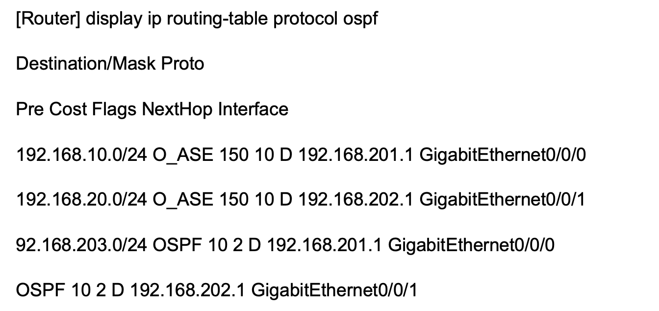
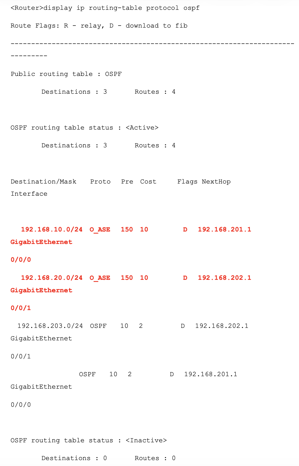
从Router的路由表可以看出,路由192.168.10.0/24的下一跳是192.168.201.1也就是SW1,而路由192.168.20.0/24的下一跳是192.168.202.1也就是SW2。
测试数据走向
现在我们做几个测试:
PC ping Server1及Server2都已经能够ping通。
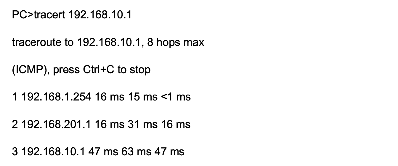
从PC tracert Server1的回显我们能看出,流量走的是Router>SW1>Server1这条路径。
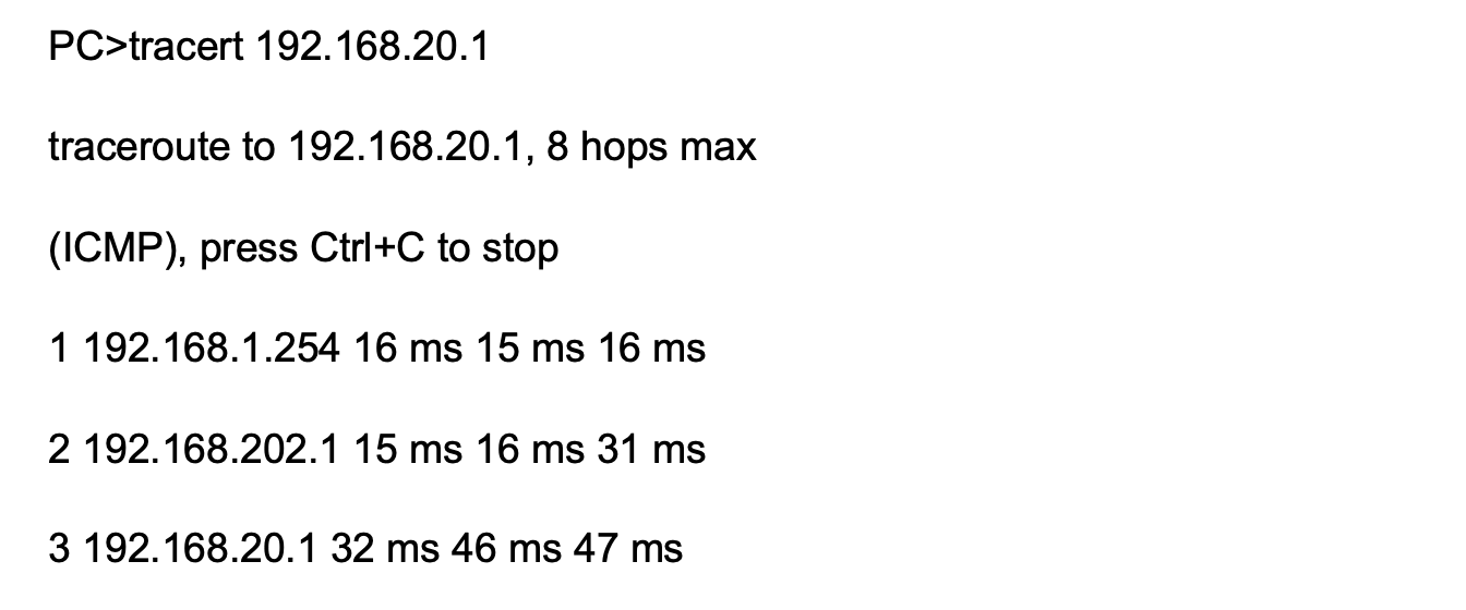
PC访问Server2走的是Router>SW2>Server2这条路径。
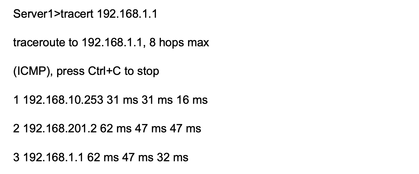
再去Server1及Server2上面看看:
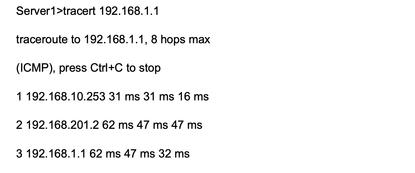
Server1访问PC的流量走的路径是:SW1>Router>PC。
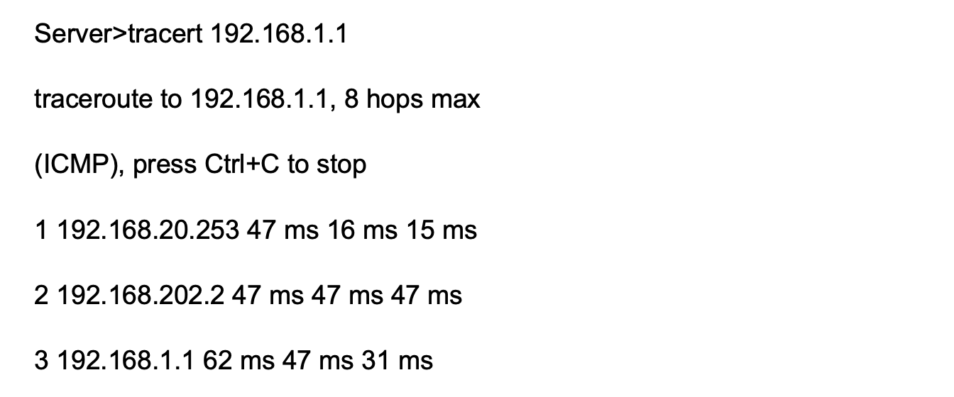
Server2访问PC的流量走的路径是:SW2>Router>PC。
因此当网络正常时的流量走向就已经满足需求了。现在再看看当网络发生故障时的现象。我们将SW1的GE0/0/21接口shutdown,然后再做几个测试:
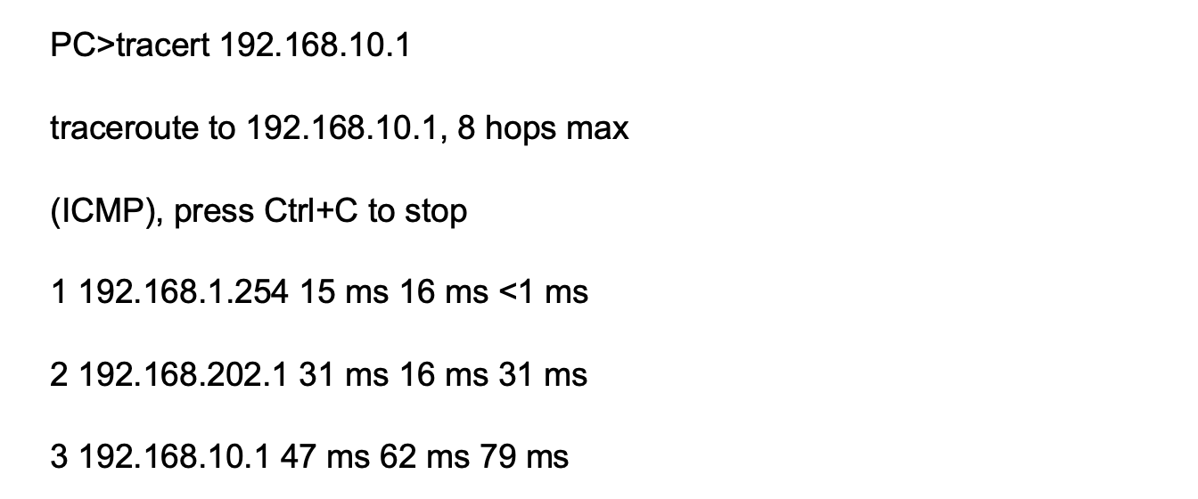
从PC tracert Server1的回显可以看出,流量切换到了SW2上。
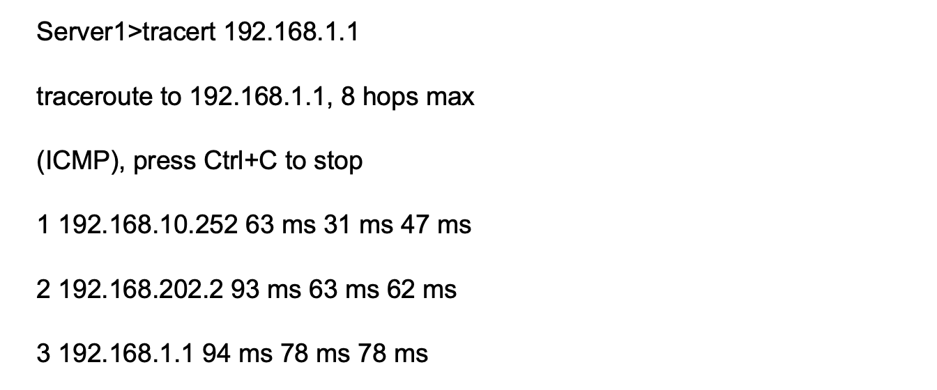
而Server1到PC的流量也切换到了SW2上。至此,整个实验就完成了。
验证结果
在Ruter上查看ospf协议的路由表。
基础配置如下:
sysname SW3
#
vlan batch 10 20
#
stp region-configuration
region-name huawei
instance 1 vlan 10
instance 2 vlan 20
active region-configuration
#
interface GigabitEthernet0/0/1
port link-type access
port default vlan 10
#
interface GigabitEthernet0/0/2
port link-type access
port default vlan 20
#
interface GigabitEthernet0/0/23
port link-type trunk
port trunk allow-pass vlan 10 20
#
interface GigabitEthernet0/0/24
port link-type trunk
port trunk allow-pass vlan 10 20
#
return
五、SW1的主要配置文件:
#
sysname SW1
#
router id 192.168.255.11
#
vlan batch 10 20 201 203
#
stp instance 1 root primary
stp instance 2 root secondary
#
stp region-configuration
region-name huawei
instance 1 vlan 10
instance 2 vlan 20
active region-configuration
#
interface Vlanif10
ip address 192.168.10.253 255.255.255.0
vrrp vrid 10 virtual-ip 192.168.10.254
vrrp vrid 10 priority 120
#
interface Vlanif20
ip address 192.168.20.253 255.255.255.0
vrrp vrid 20 virtual-ip 192.168.20.254
#
interface Vlanif201
ip address 192.168.201.1 255.255.255.0
#
interface Vlanif203
ip address 192.168.203.1 255.255.255.0
#
interface GigabitEthernet0/0/20
port link-type trunk
port trunk allow-pass vlan 10 20 203
#
interface GigabitEthernet0/0/21
port link-type access
port default vlan 201
#
interface GigabitEthernet0/0/22
#
interface GigabitEthernet0/0/23
port link-type trunk
port trunk allow-pass vlan 10 20
#
interface GigabitEthernet0/0/24
#
interface NULL0
#
ospf 1
import-route direct route-policy vlanif10and20
area 0.0.0.0
network 192.168.201.0 0.0.0.255
network 192.168.203.0 0.0.0.255
#
route-policy vlanif10and20 permit node 10
if-match interface Vlanif10
apply cost 10
#
route-policy vlanif10and20 permit node 20
if-match interface Vlanif20
apply cost 20
#
return
六、SW2的主要配置文件:
#
sysname SW2
#
router id 192.168.255.12
#
vlan batch 10 20 202 to 203
#
stp instance 1 root secondary
stp instance 2 root primary
#
stp region-configuration
region-name huawei
instance 1 vlan 10
instance 2 vlan 20
active region-configuration
#
interface Vlanif10
ip address 192.168.10.252 255.255.255.0
vrrp vrid 10 virtual-ip 192.168.10.254
#
interface Vlanif20
ip address 192.168.20.252 255.255.255.0
vrrp vrid 20 virtual-ip 192.168.20.254
vrrp vrid 20 priority 120
#
interface Vlanif202
ip address 192.168.202.1 255.255.255.0
#
interface Vlanif203
ip address 192.168.203.2 255.255.255.0
#
interface GigabitEthernet0/0/20
port link-type trunk
port trunk allow-pass vlan 10 20 203
#
interface GigabitEthernet0/0/21
port link-type access
port default vlan 202
#
interface GigabitEthernet0/0/22
#
interface GigabitEthernet0/0/23
#
interface GigabitEthernet0/0/24
port link-type trunk
port trunk allow-pass vlan 10 20
#
interface NULL0
#
ospf 1
import-route direct route-policy vlanif10and20
area 0.0.0.0
network 192.168.202.0 0.0.0.255
network 192.168.203.0 0.0.0.255
#
route-policy vlanif10and20 permit node 10
if-match interface Vlanif10
apply cost 20
#
route-policy vlanif10and20 permit node 20
if-match interface Vlanif20
apply cost 10
#
return
七、Router的主要配置文件:
#
sysname Router
#
router id 192.168.255.1
#
interface GigabitEthernet0/0/0
ip address 192.168.201.2 255.255.255.0
#
interface GigabitEthernet0/0/1
ip address 192.168.202.2 255.255.255.0
#
interface GigabitEthernet0/0/2
ip address 192.168.1.254 255.255.255.0
#
interface NULL0
#
ospf 1
area 0.0.0.0
network 192.168.1.0 0.0.0.255
network 192.168.201.0 0.0.0.255
network 192.168.202.0 0.0.0.255
#
return

openEuler 是由开放原子开源基金会孵化的全场景开源操作系统项目,面向数字基础设施四大核心场景(服务器、云计算、边缘计算、嵌入式),全面支持 ARM、x86、RISC-V、loongArch、PowerPC、SW-64 等多样性计算架构
更多推荐


 5
5 0
0- 0


 已为社区贡献1条内容

所有评论(0)